
You can perform various processing tasks, such as enhancing and annotating, on images.
Note: Any processing that you perform on an image is permanent (except for colorize, grayscale, and emboss, which are temporary). However, you can view the image in its original state by turning off any processing filters that you have applied.
To process an image
How to get there
-
From the Patient menu, under Clinical, select Imaging.
The patient record displays with the Imaging tab selected.
Tip: You can also access imaging from other clinical areas such as Chart, Progress Notes, Quick Exam, Perio, or Tx Planner.
Note: If the correct patient is not already selected, use the Patient Search field to access the patient's record.
-
On the patient's record > Imaging tab, complete one of the following:
-
View an image from the patient's image history list.
-
From the Imaging tab's menu, select Show Image History.

-
On the Images tab, select an image or series.
Examples: A full mouth series or bitewings.

-
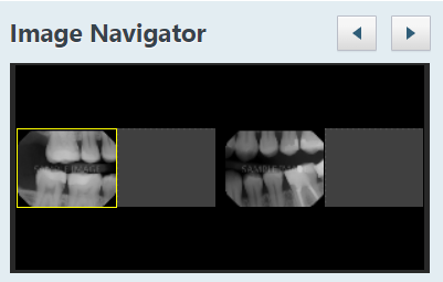
If you selected a series, under Image Navigator, clicktap an image in that series.
-
-
View one of the patient's most recent images.
-
From the Imaging tab's menu, select Show Most Recent Images.

-
ClickTap any single image (intraoral X-ray, intraoral photo, extraoral photo, or extraoral X-ray) or an image within a series (such as a full mouth series or bitewings).

-
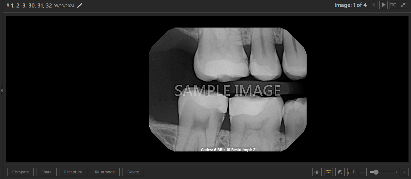
The selected image displays in the viewing area.
-
-
If not already selected, clicktap the Tools tab.

-
If the currently viewed template slot has multiple images assigned, you can clicktap the Previous or Next button
 at the top of the viewing area as needed to view another image in the stack .
Notes:
-
The Previous button is not available when viewing the top image or if there is only one image.
-
The Next button is not available when viewing the bottom image or if there is only one image.
-
-
Modify the selected image as needed, using any of the following tools:
One Click Tools

-
Enhance - Select the filter that corresponds to the anatomical structures that you want to enhance in an X-ray:
-
Not Enhanced - The image is not enhanced.
-
Entire Image - Adds a balance of sharpening and contrast levels that affects the overall sharpness and contrast.
-
For Perio - Adds a lower level of sharpening and a gray level adjustment to accentuate the subtle differences in the grayscale values of periodontal conditions.
-
For Endo - Adds a higher level of sharpening and contrast and a gray level adjustment to accentuate endodontic conditions. You may want to use this filter, for example, to help you to see the position of a file in relation to the root of a tooth when doing a root canal.
Note: To switch between viewing the image with or without an applied enhancement, clicktap the Enhancement button. If the enhancement is turned on, the button is gray
 . If the enhancement is turned off, the button is orange
  .
. -
-
Rotate - ClickTap the button that corresponds to how you want to rotate the image: 180 degrees (clockwise), 90 degrees (clockwise), or -90 degrees (counterclockwise).
-
Flip - ClickTap the button that corresponds to how you want to flip the image: Horizontal or Vertical.
-
Invert - To invert the image's colors, select the Invert checkbox. To remove the filter, deselect the checkbox.
-
Colorize (X-rays only) - To convert the image from grayscale to color, select the Colorize checkbox. To remove the filter, deselect the checkbox. This option is available only for intraoral and extraoral X-rays.
-
Grayscale (Photos only) - To convert the image from color to grayscale, select the Grayscale checkbox. To remove the filter, deselect the checkbox. This option is available only for intraoral and extraoral photos.
-
Emboss - To emboss the image, select the Emboss checkbox. To remove the filter, deselect the checkbox.
Annotations

To add a shape, complete the following:
-
Under Drawing tools, select the arrow, rectangle, or circle radio button.
-
Select an option from the Colors menu or under Last used colors.
-
Select an option from the Outline width drop-down list.
-
ClickTap and drag over a specific area of the image to create the shape.
To add text, complete the following:
-
Under Drawing tools, select the text radio button.
-
Select an option from the Colors menu or under Last used colors.
-
Select an option from the Text size drop-down list.
-
ClickTap and drag to create a rectangle with dashed borders around the area you want to draw attention to.
-
When prompted with a Text Annotation window, enter the necessary text and clicktap Create text.
To add a freehand drawing, complete the following:
-
Under Drawing tools, select the freehand radio button.
-
Select an option from the Colors menu or under Last used colors.
-
Select an option from the Outline width drop-down list.
-
ClickTap and drag over a specific area of the image to create the drawing.
Tips:
-
To remove an annotation, clicktap Undo.
-
To remove all annotations, clicktap Clear All.
-
When you select an item in the Annotations list, the corresponding annotation on the image is highlighted in white.
-
To switch between showing and hiding the annotations, clicktap the Select object(s) to Display
 icon and select/deselect the Annotation checkbox as necessary, then clicktap Confirm.
-
To switch between showing and hiding annotations and measurements for X-rays, photos, or 3D volumes, clicktap the Annotations/Measurements
 icon. The icon is only available if an annotation or a measurement has been applied to the image.
 -
For 3D volumes, freehand drawings are added to the specific 3D image slice you are currently viewing. To view an annotation on a slice that is not currently being displayed, clicktap that annotation in the Annotations list.
Measurements

Important: Distance and Angle measurements are calculated from specified points after calibration from an object with a known length. Image resolution, displayed size, inherent image quality, and proper calibration all affect the accuracy of the measurement results. However, the factors that have the greatest effect on the overall precision of a measurement are the accuracy of the calibration and selection of the start and end points of the actual line or angle to be measured. Using the calibration results, you can decide as to whether the overall accuracy achieved is correct for the measurement.
Warning: It is your responsibility to properly calibrate prior to clinical measurements and to determine if the accuracy achieved is within the error range required.
Note: Some digital sensors have a known pixel size for images, so no calibration is needed. Other digital sensors do not have a known pixel size for images, so calibration is needed prior to drawing measurements. For TWAIN sources that you have specified a known pixel size in the acquisition agent preferences, no calibration is needed.
To add measurements for an X-ray or photo, complete the following:
-
(If calibration is required) To calibrate distance measurements using an object of known size in the image, clicktap Calibrate. ClickTap the first (starting) point of the known-length object on the image where you want to start measuring and drag to another point on the known-length object. Change the length of the Standard for calibration as needed to the correct number of millimeters for the known length.
Perform the calibration step until you are comfortable that you can measure the calibration object accurately and that the displayed results have the accuracy needed. Now that you have defined the length of the segment, all measurements will be calculated respective to that calibration.
Note: For most sensors that integrate directly with Ascend Academic Imaging, it may not be necessary to calibrate images taken with those sensors.
-
ClickTap Measurements.
Tip: If calibration is not required, Measurements is selected by default.

-
ClickTap Add New Measurement, then clicktap and drag on the image to create a yellow line with start/end points. Repeat as necessary to create additional lines that are connected to the previous line's end point.
Tips:
-
To remove the last measurement, clicktap Undo.
-
To remove all measurements, clicktap Clear All.
-
To show the calculated length of each line segment, select the Show segment length (SL) checkbox.
-
To show the calculated angle where two line segments meet, select the Show angle (A) checkbox.
-
When you select an item in the Measurement list, the corresponding measurement on the image is highlighted in yellow. You can add connected lines by clickingtapping various areas on the image. You can remove connected lines in reverse order by clickingtapping Undo.
-
To switch between showing and hiding the lines and their calculated lengths and angles, clicktap the Select object(s) to Display
icon and select/deselect the Measurement checkbox as necessary, then clicktap Confirm. -
To switch between showing and hiding all annotations, measurements, and Detect AI findings (if applicable) for the image, clicktap the Show/hide annotations and measurements
icon. The icon is only available if an annotation, measurement, or Detect AI analysis has been applied to the image. -
For 3D volumes, to view a measurement on a slice that is not currently being displayed, clicktap that measurement in the Measurement list.
-
Any warning text for known pixel size measurements displays below the Measurement list.
Density (Line)
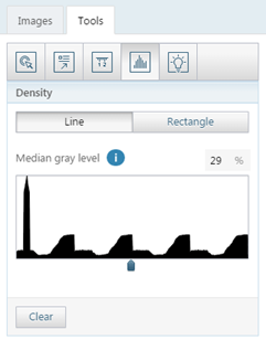
Important: Density measurements are calculated from specified points on the image and are reported from the actual pixel values selected. Image resolution, displayed size, and inherent image quality can all affect the accuracy of the Density measurement. However, the factor which has the greatest effect on the overall precision of a density measurement is the accuracy of the selected point or points to be measured.
To get the density (gray level) from one point to another on the image (X-ray images only), complete the following:
-
ClickTap Line.
-
ClickTap a point on the image, then another point to create a line.
A graph of the gray levels along the specified line displays, and the Median gray level is indicated.
Tip: To remove the density line, clicktap Clear.
Density (Rectangle)

To get the density (gray level) of a rectangular area on the image (X-ray images only), complete the following:
-
ClickTap Rectangle.
-
ClickTap and drag to create a rectangle.
The Median gray level is indicated.
Spotlight

To add a spotlight, complete the following:
-
Select one of the Effects: Invert, Colorize (for X-ray images only), Zoom x2, Sharpen, or Contrast.
-
Move the Spot size slider to specify the size of the spotlight.
-
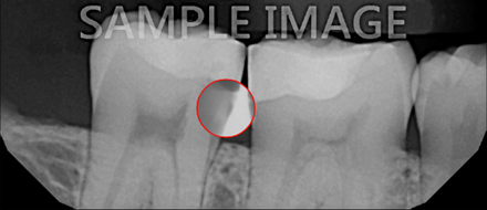
ClickTap a specific area of the image to place the spotlight with a red border:
Invert
Colorize

Zoom x2

Sharpen

Contrast

-
To move the spotlight, clicktapanother area of the image.
-
To suspend the spotlight on the image so that you can add other spotlights, clicktap Suspend. The border of the spotlight turns blue.

-
Repeat Steps a-e as needed to add additional spotlights.
Tip: To remove all spotlights, clicktap Clear Suspended, or select another processing tool.
-
-
(Optional) Adjust the brightness and/or contrast as necessary.
-
ClickTap the Brightness/Contrast icon.

-
Complete any of the following:
-
ClickTap and drag the Brightness slider to decrease or increase the brightness.
Tip: You can also clicktap and drag up or down in the viewing area to decrease or increase the brightness.
-
ClickTap and drag the Contrast slider to decrease or increase the contrast.
Tip: You can also clicktap and drag left or right in the viewing area to decrease or increase the contrast.
Tip: To reset the brightness and contrast levels to their default states, clicktap the Reset to default link.
Note: If you change the brightness or contrast, the Brightness/Contrast icon becomes orange
 .
. -
-
Comments
0 comments
Please sign in to leave a comment.